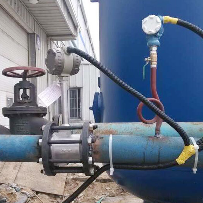
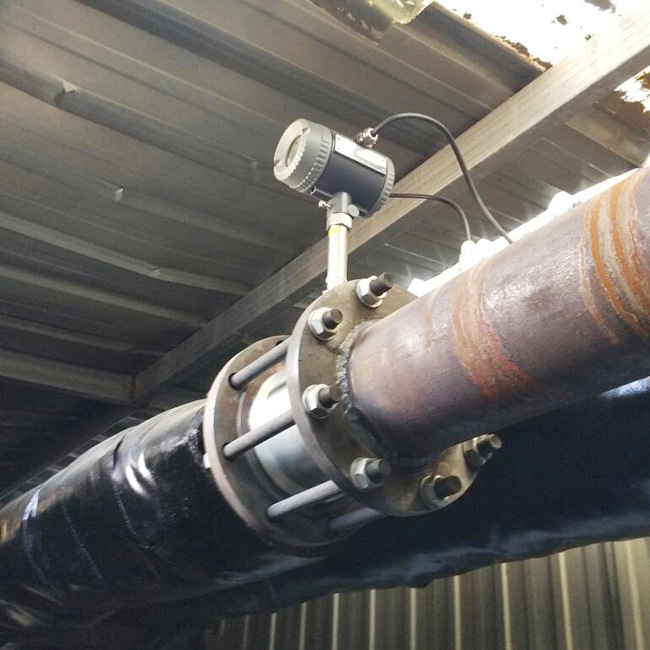
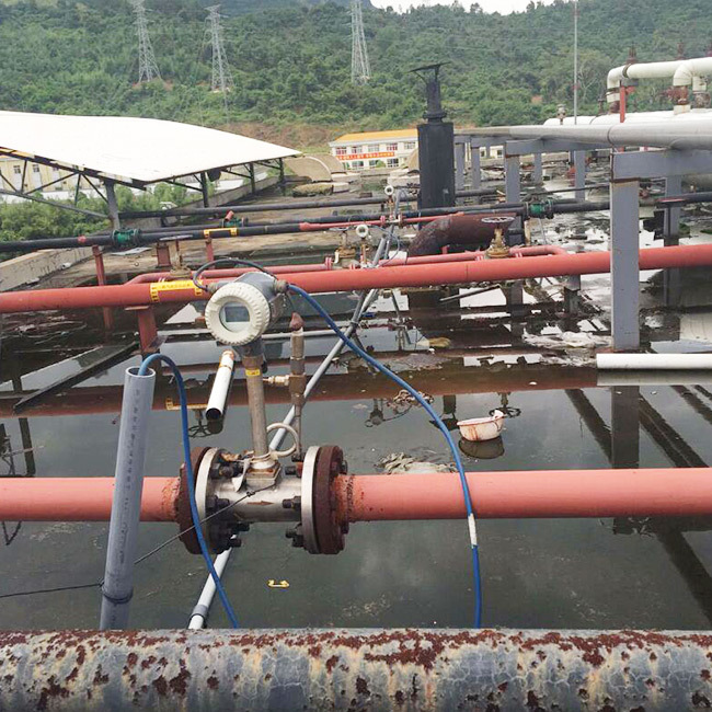
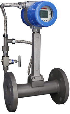
Vortex Flow Meter
LUGB & LUCB Vortex flowmeter work on the principle of generated vortex and relation between vortex and flow by theory of Karman and Strouhal, which specialize in measurement of steam, gas and liquid of lower gas and vapor even turbid liquid including micro grain and impurity. Vortex Flowmeter is on the principle of Karman Street, to measure liquid, sides with opposite directions of rotation, Vortices frequency is directly proportional to medium velocity. Through numbers of vortices that is measured by sensor head, medium velocity is calculated, plus flowmeter diameter, final volume flow come out.
LUGB-Vortex Flow Meter
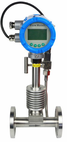
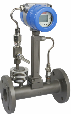
DESCRIPTION
The vortex flowmeter is used for measuring the flow velocity of gases or liquids in pipelines flowing full. The measuring principle is based on the development of a Karman vortex shedding street in the wake of a body built into the pipeline.
The periodic shedding of eddies occurs first from one side and then from the other side of a bluff body (vortex-shedding body) in stalled perpendicular to the pipe axis. Vortex sheddi ng generates a so-called "Karman vortex street" with alternating pressure conditions whose frequency is proportional to the flow velocity.
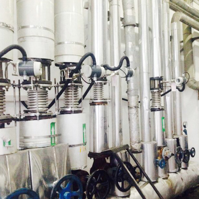
APPLICATION
- Boiler industry( Steam measurement)
- Compressed air industry
- Textile industry
- Paper Industry
- Heating industry
- Metallurgical industry
- Plastics processing