Variable area flowmeter
Variable area flowmeter is intended for fluid measurement in most industries including water, chemicals and additives, solvents, hydrocarbons, lubricants, superheated steam, food (beverages), air and industrial gases.
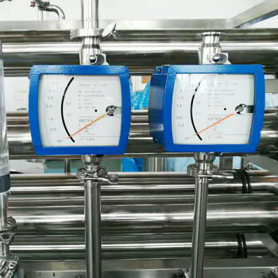
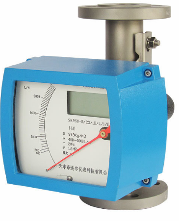
There are two basic components of variable area flowmeter: 1) The Detector, which includes the flow tube, float, and 2) The Converter, which is the mechanical display or electronic device responsible for signal processing, flow calculation, display and output signals.
The materials of construction of the wetted parts (pipe and float) should be appropriate for the specifications on the intended type of service. Review of the compatibilities consistent with the specifications is recommended.
All SURE’s variable area flowmeters are factory tested and calibrated. A calibration certificate is included in the shipment of each meter.
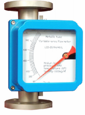
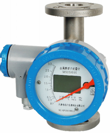
DESCRIPTION
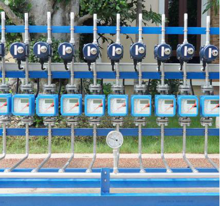
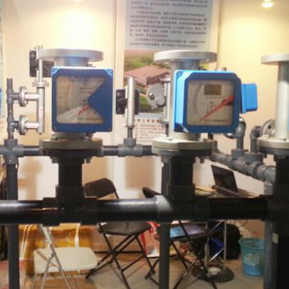
The variable Area Flow meter is an instrument for measuring the flow of liquids or gases in pipelines. It includes a vertical tube through which the fluid flows whose diameter increases from the bottom to the top and a float which can move vertically in the tube. As the flow increases this float moves to a higher position until its resistance to the fluid flow is balanced by th?float's buoyed weight in the fluid, a value which is constant and independent of the flow rate. The position of the iloat is a measure of the flow rale. The flow rate values can be read on a scale.
FEATURE
-Mechanical display and LCD display
-Robust and universal
-The short-stroke design allows the measurement of high flow
rate using a relative short metering tube
-Special application is for hazardous, dangerous or aggressive
fluid, for high temperature and high pressure rates
-All stainless steel design provides a safe measurement of a
variety of liquids, gases and sleam- The measuring section
can be equipped with a heating jacket
-Standard rotameter is mounted in a vertical pipeline with flow
direction upwards
APPLICATION
- Gas supply equipment
- Electric power
- Petroleum
- Chemical
- Metal
- Medical