Quantity: | |
---|---|
Coriolis Mass Flow Meter
The mass flowmeter is composed of two parts, the sensor and the transmitter. The mass flow meter is equipped with a digital transfer device, which is based on a digital signal processor (DSP), integrated with digital close-loop vibration controlling (DLC) signal processing, calculating and diagnostic functions of sensor, and provides high measuring accuracy, wide range ability and excellent reliability for you. Online node-configuration, faults diagnosis and data recording can be carried out directly through communication with a communicator by HART or by PC through Modbus. The flow meter will not only calculate process volume flow rate, accumulated volume and component proportion. The TS Series flowmeter can also provide mass flow rate, density and temperature online and in real-time.
SCM-Coriolis Mass Flow Meter
PRODUCT PRINCIPLE AND OVERVIEW
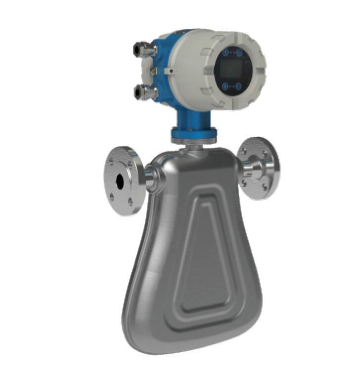
SCM-Series Coriolis Mass Flow Meter directly measures the ”Mass”of the medium with high accuracy based on the Coriolis Principle ( Coriolis Force). The accuracy would not be affected by any factors like the temperature, pressure, density, viscosity,
etc. And the compensation calculation is not required. The Coriolis Mass Flow Meter consists of two parts: the Senor and the Transmitter. The Corioils Mass Flow Meter is designed and produced based on the national standard of explosion-proof standards. The Explosionproof standard is Exd ib li Ct5 Gb.
DESCRIPTION
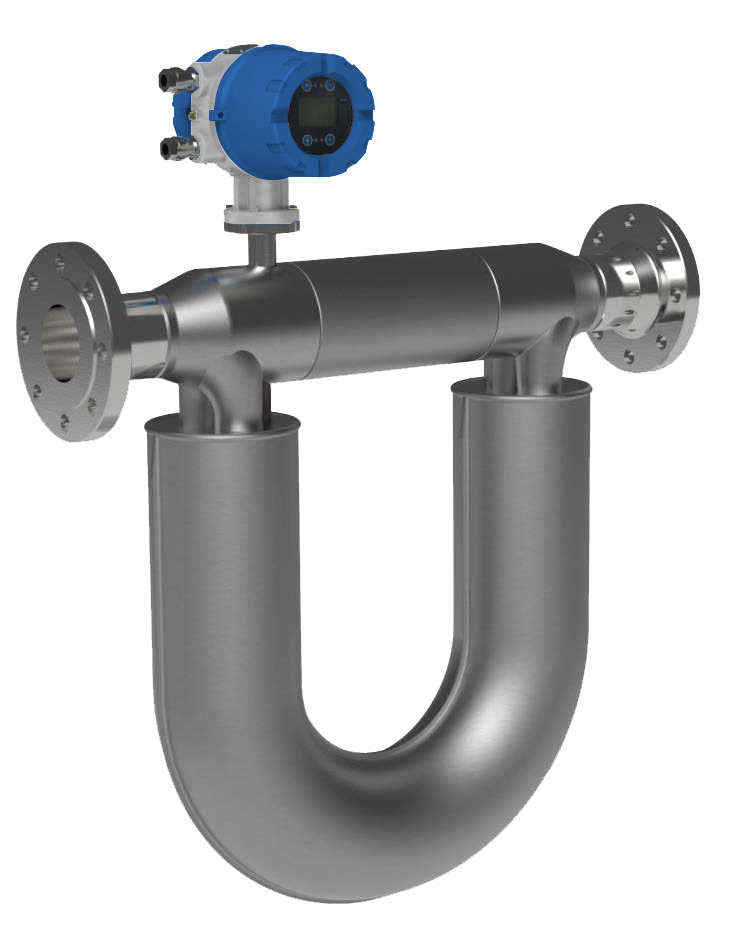
Coriolis Mass Flow Meter could directly measure the “ Mass”of the liquid. And the accuracy is the highest among all types of flow meter, saying, 0.1 -0.2%. The range of application is very large, and it could be used for the medium that difficult to be measured, like, high temperature, high pressure, high viscosity, double phases, triple phases. The requirements for the installation are low, the straight pipe requirement in front of and behind the Coriolis Mass Flow meters are low. They are more reliable, stable, and maintenanee level is low.
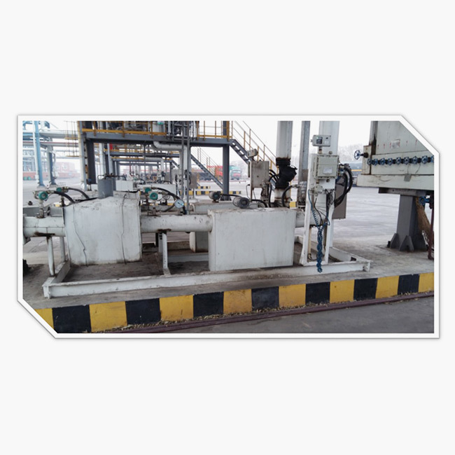
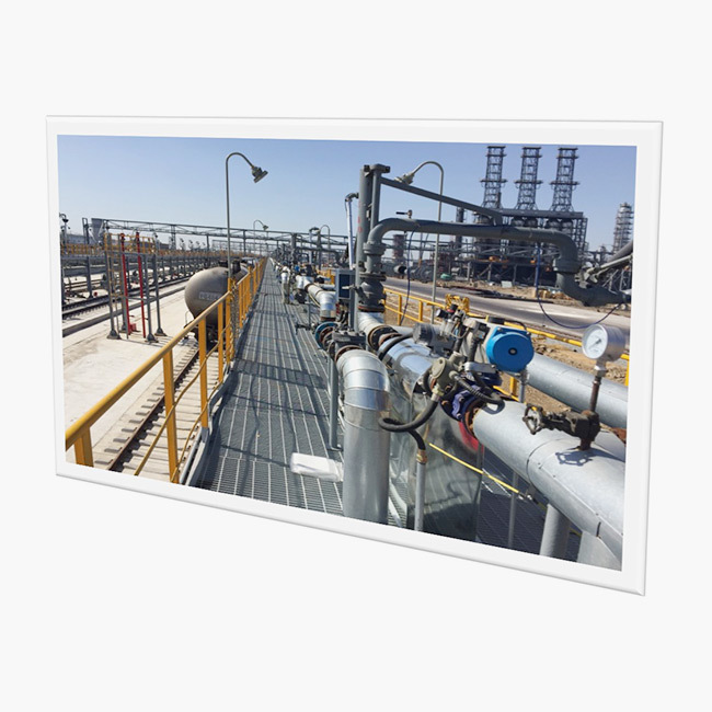
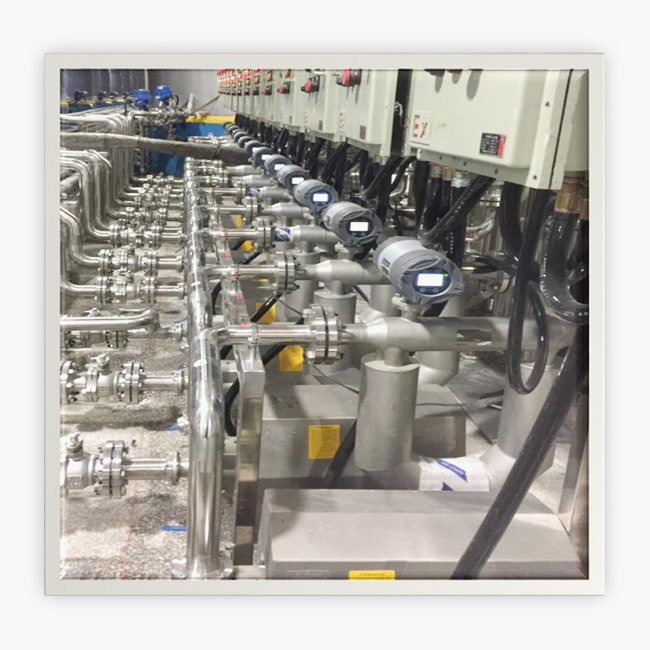
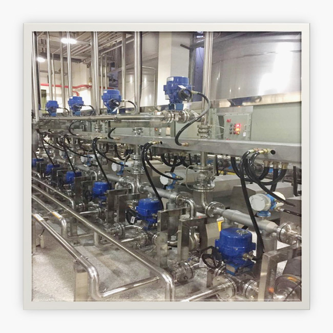
APPLICATION
TECHNICAL DATA
Application | Suitable for liquid.gas. liquid-sottd. Liquid-gas mass measurement or volume measurement |
Material of Pipeline | SS316L/ Hastelloy HC |
Pressure | Refer to chart shown above. |
Medium Temerature | -5O℃~15O℃ -50uC-250℃ -50℃~350℃ -100℃-350℃ |
Enviroment Temperature | Sensor:-4O℃-I5O℃: Transmitter:-20℃-70℃ |
Flow Rate MeaAccuracy | 0.2%; 0.1% optional |
Density Measurement Accuracy | 0.002g/cm3;0.001g/cm3 optinal |
Repeatability | 0,10% Flow Rate? i/2(Zaro Point Stability/ Flow Rate)'1OO]% flow rate |
Output Signal | 4*20mA load Resislance<500Q( instantaneous or Densily optional) 0- 10kHz insianianeous Flow Rale pulse signal |
Explosion-proof Symbol | ExdibllCT5Gb |
FLOW RANGE
V Type
Specification | DN (mm) | Liquid Flow Range (kg/h) | K - gas coefficient |
SCM-V-005 | 5 | 600 | 60 |
SCM-V-015 | 15 | 6000 | 70 |
SCM-V-025 | 25 | 18000 | 700-25 |
Note: gas flow range = liquid flow range x gas process density/K |
U Type
Model | DN (mm) | Liquid Flow Range (kg/h) | K - gas coefficient |
SCM-U-001N | 1 | 20 | 60 |
SCM-U-002N | 2 | 60 | 60 |
SCM-U-005N | 5 | 300 | 70 |
SCM-U-010N | 10 | 1000 | 80 |
SCM-U-015N | 15 | 6000 | 90 |
SCM-U-025N | 25 | 10000 | 140 |
SCM-U-040N | 40 | 20000 | 140 |
SCM-U-040H | 40 | 30000 | 140 |
SCM-U-050N | 50 | 30000 | 140 |
SCM-U-050H | 50 | 60000 | 160 |
SCM-U-080N | 80 | 60000 | 160 |
SCM-U-080H | 80 | 180000 | 215 |
SCM-U-100N | 100 | 100000 | 200 |
SCM-U-100H | 100 | 280000 | 230 |
SCM-U-150N | 150 | 300000 | 230 |
SCM-U-150H | 150 | 640000 | 240 |
SCM-U-200N | 200 | 1100000 | 250 |
SCM-U-250N | 250 | 1800000 | 300 |
Note: gas flow range = liquid flow range x gas process density/K |
MODEL SELECTION
Model | Stuffix Code | Description | ||||||||||
SCM- | 1 | 2 | 3 | 4 | 5 | 6 | 7 | 8 | 9 | 10 | 11 | Coriolis Mass Flowmeter |
Type | V | V Type | ||||||||||
U | U Type | |||||||||||
Diameter | XXX | Stand for diameter | ||||||||||
001:DN1; 010:DN10 | ||||||||||||
100:DN100; | ||||||||||||
Signal Output | 1 | 4-20mA/0-10KHz | ||||||||||
Communication | 1 | RS485 | ||||||||||
2 | Hart | |||||||||||
3 | PF | |||||||||||
4 | FF | |||||||||||
5 | None | |||||||||||
Pressure Rating | 16 | 1.6Mpa | ||||||||||
40 | 4.0Mpa | |||||||||||
63 | 6.3Mpa | |||||||||||
XX | On request(10Mpa,16Mpa are for options) | |||||||||||
Temperature Rating | T1 | -50...+150℃ | ||||||||||
T2 | -50...+250℃ | |||||||||||
T3 | -50...+350℃ | |||||||||||
T4 | -200...+150℃ | |||||||||||
Wet Part Material | S6 | SS316 | ||||||||||
HC | Hastelloy Alloy C | |||||||||||
XX | On request | |||||||||||
Accuracy Rating | 1 | 0.10% of rate | ||||||||||
2 | 0.20% of rate | |||||||||||
XX | On request | |||||||||||
Connection | AXX | ANSI Flange;A15:ANSI 150#;A30:ANSI 300#... | ||||||||||
DXX | DIN Flange;D16:DIN PN16;DN25:DIN PN25... | |||||||||||
JXX | JIS Flange;J10K:JIS 10K;J20K:JIS 20K... | |||||||||||
TRC | Tri-clamp type(Sanitary connection) | |||||||||||
THR | Thread connection | |||||||||||
Body Material | S4 | SS304 | ||||||||||
S6 | SS316 | |||||||||||
Structure | S | Compact type with local display | ||||||||||
L | Remote display include bracket | |||||||||||
Power Supply | 0 | 24V DC | ||||||||||
1 | 220V AC |