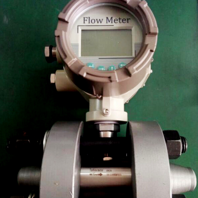
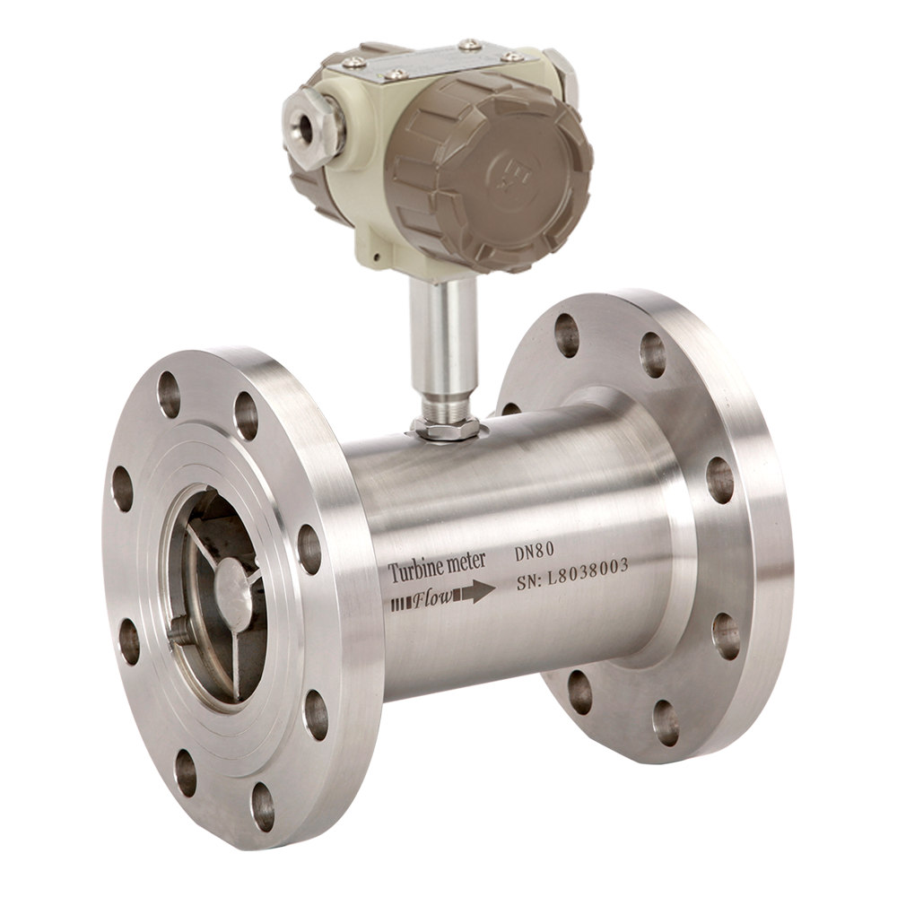
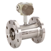
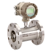
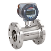
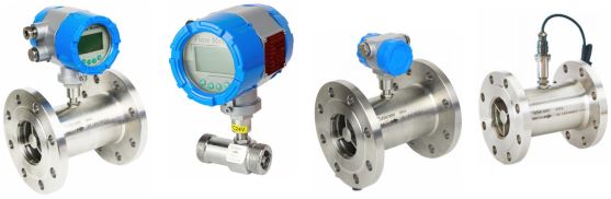
Liquid Turbine Flow Meter
LWGY series turbine flow meters have the features: high accuracy, good repeatability, convenient installation/maintenance, simple structure etc.
Liquid flows through the turbine housing causing an internal rotor to spin. As the rotor spins, an electrical signal is generated in the pickup coil. This signal is converted into engineering units (liters, cubic meters, gallons etc.) on the local display where is applicable. Optional accessory modules can be used to export the signal to other equipment.
Upon receipt, examine your meter for visible damage. The turbine is a precision measuring instrument and should be handled carefully. Remove the protective plugs and caps for a thorough inspection. If any items are damaged or missing, contact Sure
Make sure the turbine flow model meets your specific needs. For your future reference, it might be useful to record this information on nameplate in the manual in case it becomes unreadable on the turbine. Refer to the nameplate for your customized product’s specification.
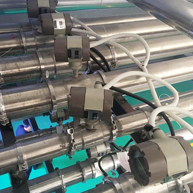
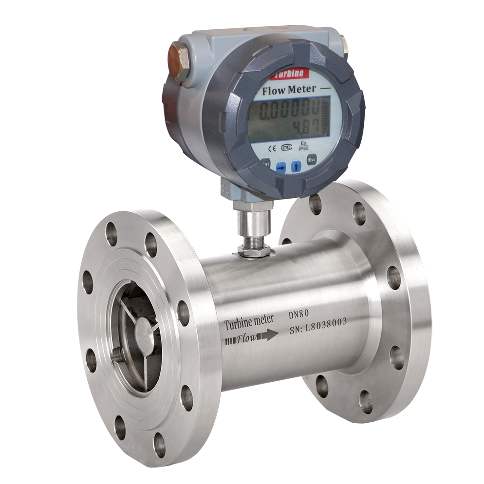
OPERATING PRINCIPLE
Fluid entering the meter first passes through an inlet flow straightener that reduces its turbulent flow pattern. Fluid then passes through the turbine, causing the turbine to rotate at a speed proportional to fluid velocity. As each turbine blade passes through the magnetic field generated by the meter's magnetic pickup, an AC voltage pulse is generated. These pulses provide an output frequency that is proportional to volumetric flow.
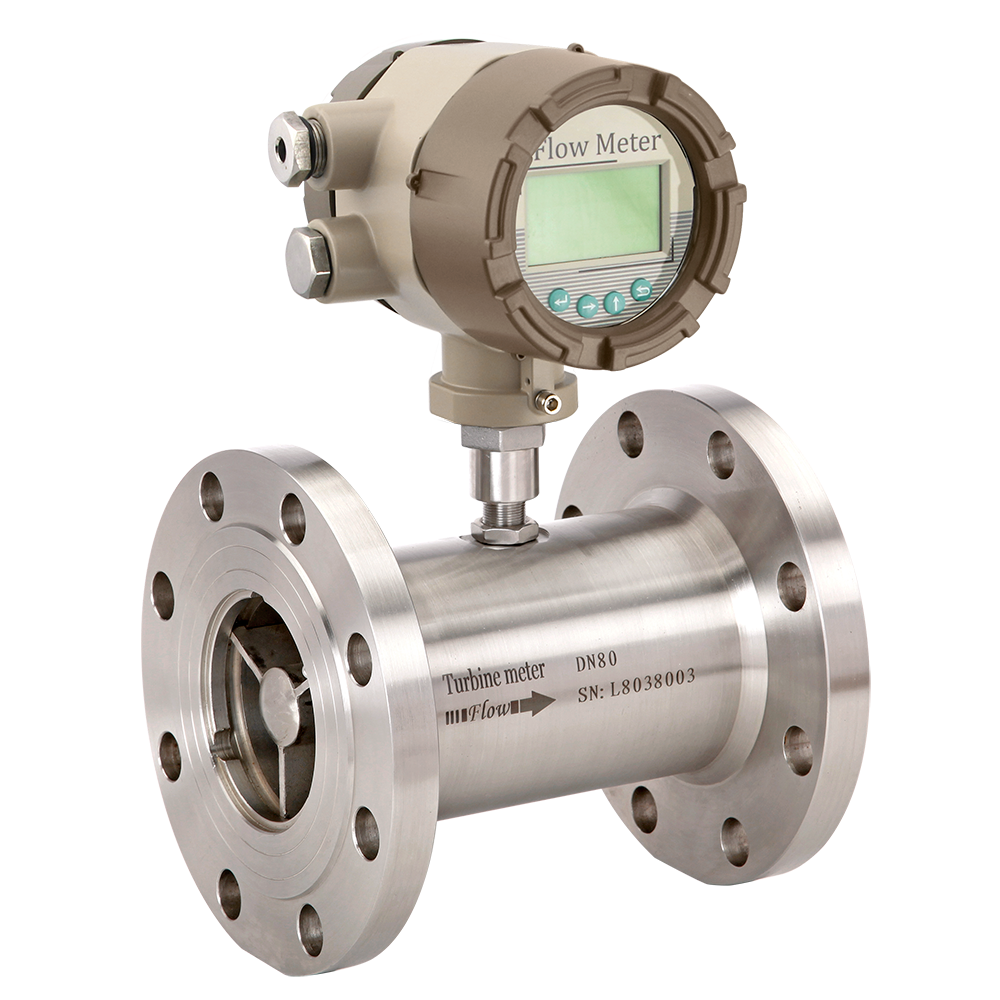
LWGY-Liquid Turbine Flow Meter
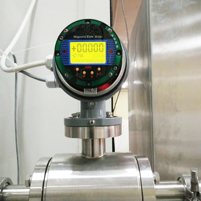
DESCRIPTION
The liquid turbine flow meter in the series LWGY are specially designed for usage in water, diesel, gasoline and other fluid measurement and control systems. They operate according to the turbine principle, i.e. the speed of an impeller turning in the fluid flow is measured and converted into pulse or 4-20mA signals
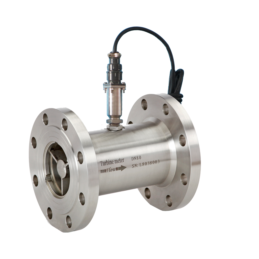
Technical Data
-Output: Pulse; 4-20mA
-Accuracy:±1.0 of Rate;±0.5% of Rate
-Operating Temp.: -2O..,+6O℃
-Fluid Temp.: -2O...+ 15O℃
-Body Material: SS304; SS316
-Rotor Material: 2Cr13;CD4MCu
-Bearing Material: Tungsten Carbide
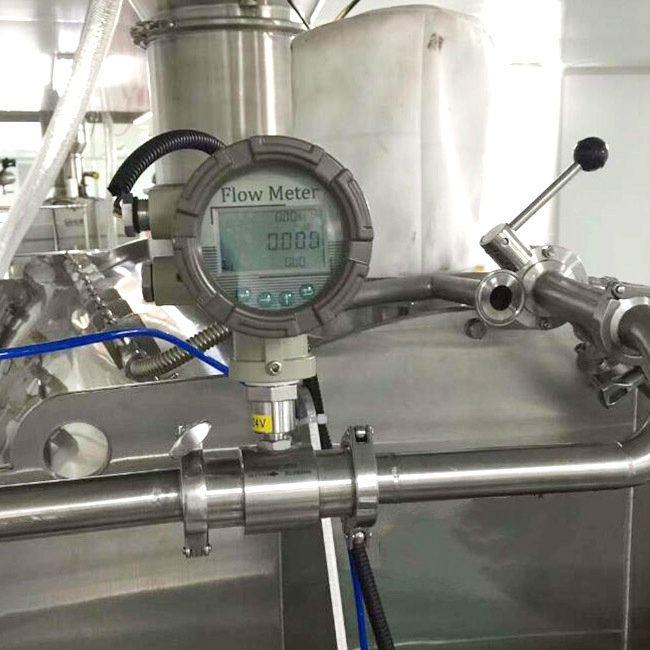
APPLICATION
- Petrochemical/energy industry
- Hydraulic/lubrication system
- Oil / gas industry
- Test systems
- Distilled water
- Clean water
- Food and beverage industry